Free 2-day Shipping On Millions of Items. How to wire multiple outlets? How do you wire a GFCI switch? Shut off power to the circuit at the breaker box.

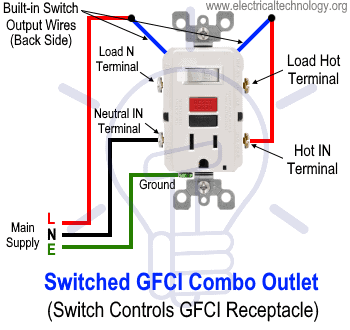
Tape or lock the box with a warning label to prevent anyone. They can work in conjunction with one another, or they can be connected and used independent of each other. Remove the mounting screws holding. A combo device is the combination of switch and outlet in the same enclosure box. The builtin switch can be wired to control the receptacle in the enclosure box.
The switch can be also wired through a jumper wire where the switch will control an additional load point such as lighting point. A switch and outlet combo can be configured in several ways. Switch can control the light only. The following diagrams show each wiring configuration. Ground connection diagramis shown separately.
Scott, a combo switch outlet will require the set of wires that are for the switched device, in this case the disposal, and the outlet will require a hot, neutral and ground wire. The switch can control your lights, the switch can control the outlet , or the switch can control both your lights and the outlet. For example: say your countertop appliances are hogging all of the outlets in your kitchen.
A wiring diagram is a simplified traditional photographic representation of an electric circuit. It reveals the parts of the circuit as streamlined forms, and also the power as well as signal connections between the tools. There is a break way fin tab intact to the line (hot) side which can be removed if switch is needed to control additional load otherwise, a jumper wire can be added between the switch load terminal and lower line terminal (while removing the break away fin tab) hence, it will control the.
Notice: Installing additional outlet wiring should be done with a permit and be inspected. Connect the last switch in the usual manner, looping the wire around the screw in a clockwise direction. Combination switches are always installed with through- switch wiring and never with end-line wiring. That means two or three cables enter the box. This wiring diagram illustrates adding wiring for a light switch to control an existing wall outlet.
The source is at the outlet and a switch loop is added to a new switch. The hot source wire is removed from the receptacle and spliced to the red wire running to the switch. From sensor guide lights to multi. This page contains wiring diagrams for household light switches and includes: a switch loop, single-pole switches, light dimmer, and a few choices for wiring a outlet switch combo device. Also included are wiring arrangements for multiple light fixtures controlled by one switch , two switches on one box, and a split receptacle controlled by two.
They help simplify electrical installations in areas such as industrial buildings, factories, and plants. What's the correct wiring please? Wiring this way got me a dead outlet. In the first case, the switch controls the outlet and nothing else. To make this happen, connect the black circuit wire to the brass screw on the device, the white wire to the chrome screw and the ground wire to the green ground screw.
The second method of wiring middle-of-run receptacles is to connect them to the circuit wires via pigtails. A pigtail is a short length of wire that runs from a hot or neutral screw terminal on the receptacle to the circuit wires, which are joined together in the outlet box with a wire connector. If you want an outlet at the switch box, you need to bring a neutral from the light box.

No comments:
Post a Comment
Note: only a member of this blog may post a comment.