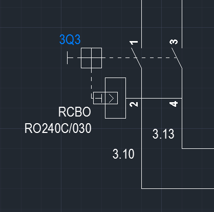
Free Vector Symbols. A circuit diagram ( electrical diagram , elementary diagram , electronic schematic) is a graphical representation of an electrical circuit. A pictorial circuit diagram uses simple images of components, while a schematic diagram shows the components and interconnections of the circuit using standardized symbolic representations.

Electric circuit , path for transmitting electric current. In some cases a diagonal line may be used which. Component symbols in a circuit diagram are usually placed horizontally or vertically. On very rare occasions a component. Design circuits online in your browser or using the desktop application.
A circuit diagram is a visual display of an electrical circuit using either basic images of parts or industry standard symbols. Circuit diagrams are drawn. Symbol usage depends on the audience viewing the diagram. These two different types of circuit diagrams are called pictorial (using basic images) or schematic style (using industry standard symbols).
How do I create a wiring diagram? What are the different types of electrical diagrams? What is an electric circuit diagram?
A wiring diagram is a simple visual representation of the physical connections and physical layout of an electrical system or circuit. It shows how the electrical wires are interconnected and can also show where fixtures and components may be connected to the system. Line diagraa one-line diagram or single-line diagram is a simplified notation for representing an electrical system.
The one-line diagram is similar to a block diagram except that electrical elements such as switches, circuit breakers, transformers, and capacitors are shown by standardized schematic symbols. See all full list on rapidtables. Official Repair Manuals Website.
We Have Almost Everything on eBay. Bay Is Here For You with Money Back Guarantee and Easy Return. An electric circuit is a closed loop with a continuous flow of electric current from the power supply to the load. Here are ten simple electric circuits commonly found around the home. Use the Electrical Engineering drawing type to create electrical and electronic schematic diagrams.
Our circuit diagram symbol library is schematic and includes many icons commonly used by engineers. Open Edraw electrical diagram maker, and this large collection of symbols are found in the Engineering category in the Available Templates list. After you start Edraw, click the icon of Basic Electrical Symbols to open the stencil that includes all shapes for making circuit diagrams. Drag the shape that you need directly onto the canvas.
MUST-READ instructable. This free electrical engineering textbook provides a series of volumes covering electricity and electronics. The information provided is great for students, makers, and professionals who are looking to refresh or expand their knowledge in this field.

Electrical symbols and electronic circuit symbols are used for drawing schematic diagram. The symbols represent electrical and electronic components. Scheme-it is a free online schematic drawing tool that will allow you to produce professional looking schematic diagrams , add corresponding part numbers, and share your schematic with others. These tools allow students, hobbyists, and professional engineers to design and analyze analog and digital systems before ever building a prototype. Ladder diagram are electrical diagrams that represents an electrical circuits in industries to document control logic systems.
It resemble a ladder which is why it is named ladder diagram. In circuit diagrams , there are many electrical symbols that are used to represent different electrical components and devices. Here is an overview of the most used symbols in circuit diagrams.
Resistor: A resistor is used to restrict the amount of current flow through a device. There are some standard symbols to represent the components in a circuits. This article gives some of the frequently used symbols for drawing the circuits. There are many electrical and electronic schematic symbols are used to signify basic electronic or electrical device.
This diagram illustrates wiring for one switch to control or more lights. The source is at SWand 2-wire cable runs from there to the fixtures. The hot and neutral terminals on each fixture are spliced with a pigtail to the circuit wires which then continue on to the next light.
No comments:
Post a Comment
Note: only a member of this blog may post a comment.